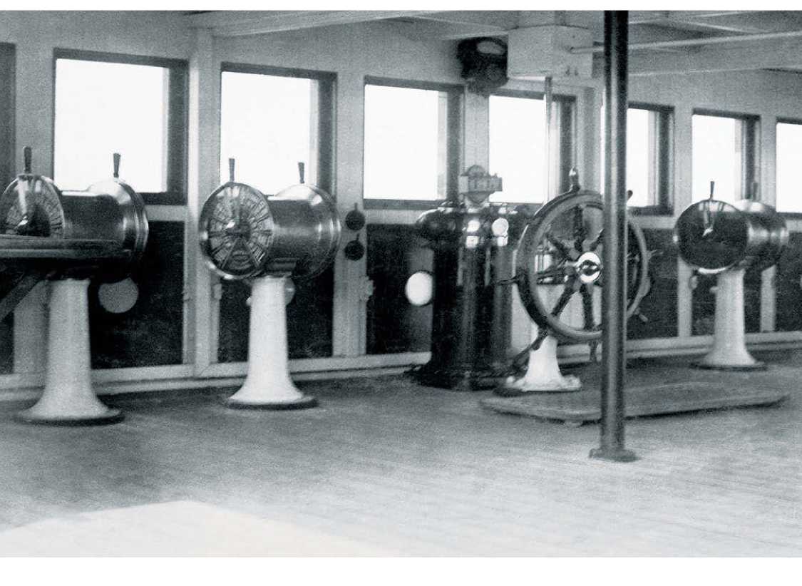
Titanic was equipped with three helms, or steering wheels. The master wheel was in the wheelhouse, from where the ship was normally steered at sea. A second wheel (usually used by the pilot or in any situation where frequent orders to the helmsman were called for) was on the navigating bridge, just forward of the wheelhouse; and the third was on the docking bridge aft. (Navigating instructions to the helmsman, by the way, might seem confusing, as “starboard the helm” meant “turn to port.” Titanic took her blow from the iceberg on the starboard side: in an attempt to avoid this, First Officer Murdoch had given Quartermaster Robert Hichens the order “hard-a-starboard,” i. e., go to port.) Titanic’s wheels were proper, solid ship’s wheels, not the tiny little metal ones of today. The wheel pedestal on Titanic’s navigating bridge was 2 feet 8 inches high and carried a teak wheel 3 feet 9 inches in diameter. The wheel in the wheelhouse was slightly smaller. Its shaft passed through the steering binnacle and was attached to the steering device.
The steering device was a telemotor manufactured by Brown Brothers of Edinburgh, and it worked on a hydraulic system, using a single cylinder forward and a corresponding cylinder at the site of the steering engine. An override restored the rudder to its central position whenever hydraulic pressure was removed. The wheels were designed

Although no photograph exists of Titanic’s wheelhouse and bridge, this of Olympic’s probably reflects that of her sister ship very accurately. The principal wheel, the ship's telegraph devices and the binnacle of the compass can all be seen clearly.
To be capable of four revolutions in either direction, at the limit of which the rudder was “hard over.” Electric helm and course indicators were fitted close to the main wheels and in clear view of the helmsman and officer of the watch. As for the steering gear, located under the poop deck aft, it was driven by twin steam engines. Great power was needed to shift the 101.5-ton rudder, which itself was thrusting broadside against a very large quantity of water whenever it moved. The spur-wheels and pinions within the steering gear assembly were manufactured by Citroen.
This 1877 diagram shows Lord Kelvin's apparatus for a transatlantic telegraph.
The mirror galvanometer (a mechanical meter which senses electric current) is the device on a tripod to the left of the drawing.


 World History


